BCD counters are widely used digital electronics components designed for decimal counting, timing control, and numerical display applications. This article explains what a BCD counter is, how a BCD counter circuit works, and the functions of common BCD counter ICs such as the 74LS90, CD4518, and 74HC390. It also compares synchronous and asynchronous BCD counters, highlights the differences between BCD and binary counters, discusses common troubleshooting issues, and explores real applications of BCD counters in display systems, industrial automation, measurement equipment, and embedded electronics.
Catalog
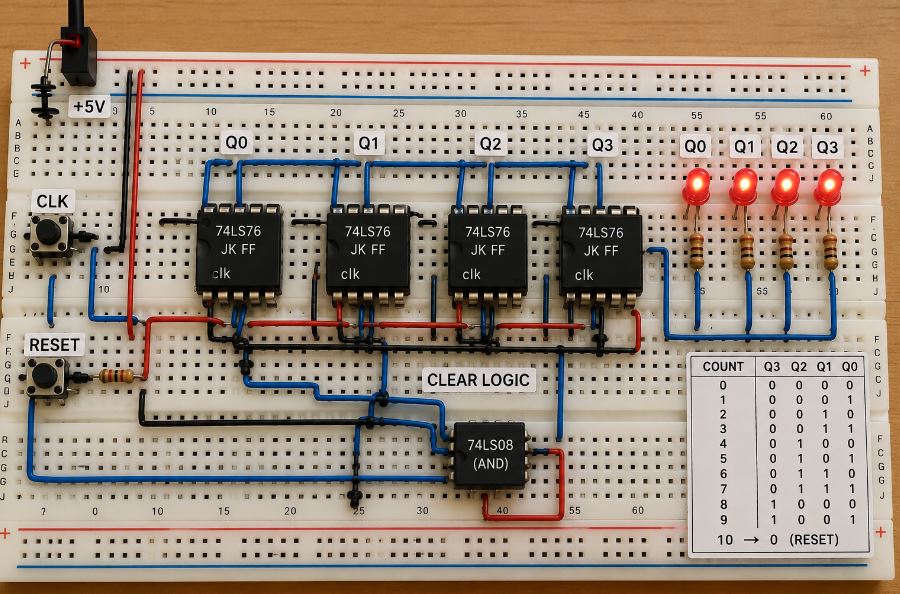
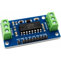
Figure 1: BCD Counter
A BCD counter, or Binary-Coded Decimal counter, is a type of digital counter that counts decimal numbers from 0 to 9 using binary output codes. It is commonly used in digital electronics because it represents decimal digits in a format that electronic circuits can process easily. Unlike a standard binary counter that continues through all binary combinations, a BCD counter only uses ten valid counting states that correspond to the decimal numbers 0 through 9. For this reason, it is also called a decade counter.
The term “BCD” means that each decimal digit is represented by a 4-bit binary number. In a BCD counting sequence, decimal values 0 to 9 are encoded as binary outputs from 0000 to 1001, while the remaining binary combinations are not used in standard BCD counting. Because BCD counters follow decimal counting logic, they are widely used in digital systems that need direct decimal number handling instead of regular binary counting.
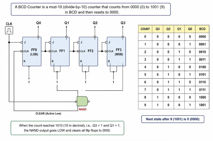
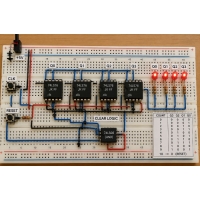
Figure 2: BCD Counter Circuit Diagram
A BCD counter circuit diagram typically includes flip-flops, logic gates, clock input connections, and reset circuitry that work together to generate a decimal counting sequence from 0 to 9. The flip-flops store the binary count values, while the logic gates detect invalid BCD states and control the reset operation. The clock input provides timing pulses that advance the counting sequence, and the reset circuitry ensures the counter returns to 0000 after reaching decimal 9. Many practical BCD counter circuits are implemented using integrated circuits such as the 74LS90, CD4518, and 74HC390 to simplify digital electronics design and reduce external component requirements.
Different BCD counter ICs are designed for specific digital electronics applications such as low-power circuits, high-speed counting systems, and up/down counting operations. Choosing the correct BCD counter IC depends on factors such as operating speed, power consumption, circuit complexity, and display compatibility.
BCD Counter
IC
|
Type
|
Main Function
|
Common Uses
|
74LS90
|
TTL Decade
Counter
|
Performs
modulus-10 counting and frequency division operations
|
Digital
clocks, timers, event counters
|
CD4518
|
CMOS Dual BCD
Counter
|
Provides dual
decimal counting with low power consumption
|
Battery-powered
devices, digital displays
|
74HC390
|
High-Speed
Dual Decade Counter
|
Supports fast
decimal counting and divide-by-10 functions
|
Frequency
counters, embedded systems
|
74LS192
|
Synchronous
Up/Down Counter
|
Allows both
incrementing and decrementing decimal counts
|
Digital
measurement systems, industrial counters
|
74LS193
|
Binary/BCD-Compatible
Counter
|
Performs
high-speed counting with up/down capability
|
Control
systems, digital logic circuits
|
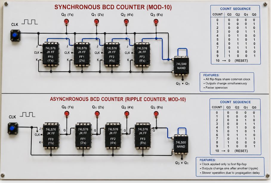
Figure 3: Synchronous vs Asynchronous BCD Counter
Synchronous and asynchronous BCD counters differ mainly in how their flip-flops receive clock signals. This difference affects counting speed, propagation delay, circuit complexity, and overall performance in digital electronics systems.
Feature
|
Synchronous
BCD Counter
|
Asynchronous
BCD Counter
|
Clock
Operation
|
All
flip-flops receive the clock pulse simultaneously
|
Flip-flops
are triggered one after another
|
Speed
|
Faster
counting operation
|
Slower due to
propagation delay
|
Propagation
Delay
|
Very low
|
Higher ripple
delay
|
Circuit
Complexity
|
More complex
logic design
|
Simpler
circuit design
|
Output
Stability
|
More stable
and accurate
|
Less stable
at high frequencies
|
Performance
|
Better for
high-speed digital electronics
|
Suitable for
low-speed applications
|
Power
Consumption
|
Slightly
higher in some designs
|
Usually lower
|
Common
Applications
|
Microprocessors,
digital timers, frequency counters
|
Basic
counters, simple digital circuits
|
Main
Advantage
|
High speed
and accurate timing
|
Easy
implementation
|
Main
Limitation
|
Requires more
logic circuitry
|
Delay
increases as count stages increase
|
BCD counters and binary counters are both used for digital counting operations, but they differ in counting sequence, output format, and system compatibility. The choice between the two depends on whether the circuit requires direct decimal output or efficient binary processing.
Feature
|
BCD Counter
|
Binary
Counter
|
Counting
Sequence
|
Counts
decimal numbers from 0 to 9
|
Counts
through all binary states
|
Output Format
|
Binary-Coded
Decimal (BCD) output
|
Pure binary
output
|
4-Bit
Counting Range
|
0000 to 1001
(0–9)
|
0000 to 1111
(0–15)
|
Reset
Operation
|
Resets after
decimal 9
|
Continues
through full binary sequence
|
Unused States
|
Binary states
1010 to 1111 are unused
|
All binary
states are used
|
Circuit
Complexity
|
More complex
due to reset logic
|
Simpler
circuit design
|
Decimal
Compatibility
|
Directly
supports decimal counting
|
Requires
binary-to-decimal conversion
|
Processing
Efficiency
|
Less
efficient for binary processing
|
More
efficient for digital processing
|
Common
Applications
|
Digital
clocks, timers, calculators, display systems
|
Computers,
microprocessors, memory circuits
|
Main
Advantage
|
Easy decimal
display interfacing
|
Faster and
more efficient binary counting
|
Main
Limitation
|
Additional
reset circuitry required
|
Not directly
compatible with decimal displays
|
Problem
|
Possible
Cause
|
Troubleshooting
Solution
|
Skipping
count values
|
Incorrect
reset logic or unstable clock pulse
|
Check reset
circuitry and clock signal stability
|
Invalid BCD
outputs
|
Wrong logic
gate connections
|
Verify
flip-flop and logic gate wiring
|
Extra
counting
|
Noise or
switch bouncing
|
Use debounce
circuits and clean clock signals
|
Unstable
operation
|
Floating
inputs or poor grounding
|
Add
pull-up/pull-down resistors and improve grounding
|
Incorrect
display output
|
Faulty
BCD-to-7-segment connections
|
Check decoder
and display wiring
|
Timing errors
at high speed
|
Propagation
delay in asynchronous counters
|
Use
synchronous BCD counters for faster operation
|
Digital Display Systems
• Digital clocks – BCD counters count seconds, minutes, and hours in decimal form for accurate time display.
• Electronic timers – Used to generate readable countdown and timing sequences in industrial and consumer electronics.
• 7-segment display circuits – BCD outputs connect easily with BCD-to-7-segment decoders for direct numerical display control.
• Elevator floor indicators – Help display floor numbers clearly using decimal counting logic.
Measurement and Counting Equipment
• Frequency counters – Count input signal pulses and display frequency values in decimal format.
• Digital panel meters – Convert counting outputs into readable numerical measurements.
• Event counters – Track machine operations, object counts, or production cycles in industrial systems.
• Scoreboards and tally counters – Display scores and numerical values in sports and monitoring systems.
Industrial Automation Systems
• Production line counters – Monitor product quantities during manufacturing processes.
• Machine cycle counters – Count repetitive machine operations for automation control and maintenance tracking.
• Packaging systems – Keep track of item counts in automated packaging equipment.
• Traffic light timing systems – Control decimal-based timing sequences in traffic management circuits.
Embedded and Digital Electronics Systems
• Microcontroller interfacing circuits – Provide decimal counting outputs for embedded system applications.
• Divide-by-10 frequency dividers – Reduce clock frequencies in timing and communication circuits.
• Digital control systems – Manage counting operations in programmable electronic devices.
• Calculator and computing circuits – Support decimal number processing and display functions.
BCD counters provide reliable decimal counting operation by generating Binary-Coded Decimal outputs from 0 to 9. Their compatibility with display systems, timing circuits, and digital counting applications makes them important components in clocks, timers, frequency counters, automation systems, and embedded electronics. Understanding BCD counter circuits, IC selection, counter types, performance differences, and troubleshooting methods helps improve the design and reliability of modern digital electronics systems.
Zdieľajte tento príspevok